by
Wil Schuemann
In the last year and a half or so I did quite a modification program on an open Libelle. It impressed a number of people so we are going to talk about it today. A lot of pilots spend thousands of hours smoothing wings and sealing gaps, these are modifications that mainly help on the low speed end. The only thing that the typical pilot has done that has helped on the high speed end is add water, and that doesn't really help the efficiency of the glider.
I would like to show you that it is within your realm of capability to probe your own ship to find out where the problem areas are in the high speed region, and to show you that you can do quite a bit about it without ever touching your ship structurally or doing anything particularly drastic. In most cases you can do it with little work. At least a lot less work than say, smoothing a wing.
With the open Libelle on which I worked, I got a net thirty percent improvement in performance at one hundred knots. About fifteen percent of that improvement came quite easily. I would say several hundred hours got fifteen percent, a good thousand hours got the next ten percent and the final five was just a fluke.
I would like to spend a little time telling you about the instrumentation you need to probe your ship and what you should look for. And then at the end I will show you how it was applied to my Libelle.
In high speed drag there are two principal ways that you get losses. One is having an excessive amount of turbulent flow on the surfaces of your glider. In the high speed region, especially on the flapped sailplane, the flow on the forward half of the upper and lower surface of the wing should be laminar and on the fuselage up the region of the wing the flow should be laminar. The forward half of the tail surfaces should be laminar. If you have more area that that turbulent, you are unnecessarily losing performance.
The equipment you need to determine what part of your sailplane is laminar consists of 1/16th inch diameter plastic tubing that you get from your hobby shop and a stethoscope. The way you use it is to get into the cockpit with the stethoscope, take the tube and tape it to the side of the fuselage in the area of interest, and run it into the cockpit. Then go up and fly and listen. You will hear one of three things. If the flow is laminar, you will hear at most a gentle rustle or usually nothing. If the flow is transitioning to turbulent, you will hear a lot of little whistles either some odd tones or one predominant tone. This tells you that the boundary disturbances are beginning to get irregular or they are beginning to build up, and as they pass the end of the tube they make these little noises. When you get full transition to turbulent, you get a very loud roar. So there are three regions and the difference between the laminar quiet sound and the very loud, irregular roar that tens you the flow is turbulent is easy to determine. So every time you go up you can put one or more probes on your ship quite easily and plot on your own glider as a function of speed what areas are laminar and what areas are turbulent. If you find some areas that are unnecessarily turbulent, you can ask the question: why? Then when you do your work you know you are working on an identified problem area.
Now as to the second major area of losses in the high speed region; this is what you need to determine them. You start out in the cockpit with a syringe full of red dye. The dye is water plus food coloring plus a few drops of detergent.
Let me talk a little bit about the definition of separations. Separations occur principally in a region where the geometry of the sailplane changes too abruptly and the boundary layer leaves the surface. Downstream of that transition you always want the boundary layer to be attached to the sailplane. The typical places where you have this type of problem are at the wing roots and aft of the tail wheel. Another place that is bad on some ships is just aft of the horizontal tail and right at the rudder.
If, for instance. you wanted to probe the wing root flow you go to the area of the wing root say just above or below the wing and say half way back on the chord and drill a 1/16th inch diameter hole in the skin, through that hole you insert your 1/16th inch tube so it is flush with the outside surface of the skin. On the inside you put just a little glue to hold it in place. Then run the tube back to the syringe. Then fly at the speed and flap setting you want to investigate and just trickle a little bit of dye out into the boundary layer. It will run in a fine stream all the way back to the tail if everything is all right, if not, it will run back and start to spread around. It will eddy and show all kinds of problems. if you have that kind of a situation you are going to have to do some sealing or some filleting or something to resolve the problem.
If you take an hour or so to set up such a test, you can do one every time you fly. After a while you will know whether the flow is proper or not over your entire glider The third area turned out to be rather critical on the Libelle is not strictly a high speed problem but a general one. It relates to the fact that on most flapped gliders you don't know where to set the flaps or how to rig the ailerons. On the Libelle this is particularly true. The differential between the flaps and the ailerons should be set so as to have the optimum lift distribution all the time. To do this you need a homemade manometer (just a "U" tube with water in it) and some more tubing. (This is radio spaghetti, real inexpensive, a couple dollars per hundred feet.) The outer end of the tube is closed off by heat and a very small hole is punched in the side of it. Lay this on the wing at about 1/3 of the chord, seal it down with tape and it becomes a static port. Place 7 or 8 of these along the wing span. When you are in the air fly at one speed and check the pressure at each one of these static ports. It is not exactly this simple but essentially you should have the same pressure relative to static. You have to hook the other side of the manometer to static. You should see the same pressure at all of the various ports across the entire wing span. If you've got that you have the proper aileron, flap coupling. If you don't then it needs to be adjusted; and in the Libelle it needs to be adjusted quite a bit.
The next thing you need is this book: Fluid Dynamic Drag by Dr. Sieghard Hoerner, Tuetfingen, Greenbriar, Ricktown, New Jersey 08723. A year and a half ago I didn't know anything about aerodynamics. A fellow in the lab where I work had it on his book shelf and I picked it up and started reading. It is very practical. If you can do fifth grade math you've got all you need in the way of mathematics to understand it. It's a compilation of all the flight and wind tunnel tests that are applicable to aerodynamics from the early thirties to about 1955. The author died a short time ago so the book may not be obtainable now. It is well worth having.
Then I got a notebook and recorded a lot of data in it. Much of this did not seem to be worthwhile when I was gathering it. But after I gathered enough of it, it was amazing how I could go back and put together the story and determine performance that I never thought I could extract out of the individual data point when I took it. So it really makes a worthwhile record.
I hope I have at least shown you that there is nothing complicated about gathering this information. It takes a little bit of perseverance but the results are dramatic as can be shown by the figures.
· Lower wing surface completely turbulent at speeds over 80 knots
· Flap position and flap-aileron coupling incorrect at speeds over 65 knots
· Wing area error by manufacturer
· Forward fuselage turbulent at speeds over 80 knots
· Strong vortex shed from wing root at speeds over 70 knots
· Separation aft of tailwheel
· Lack of ventilation inlet or exhaust
FIGURE 1
Figure 1 is the list of all the problems that were identified on the open Libelle with regard to excess drag. They are not necessarily in the order of importance and without comment as to how we determined them.
The first one that we found is that the lower wing surface is completely turbulent. All the way from the leading edge to the trailing edge at speeds of over eighty knots in still air and of over sixty to sixty-five knots in turbulent air. We found this with the little probe and the stethoscope that we talked about. Then we found that the flap position and the flap-aileron coupling were incorrect at speeds over sixty-five knots. We found this by putting the static probes on the wing and measuring the pressure distribution across the wingspan.
Next, we found that the wing area was incorrectly stated by the manufacturer. There is a 7% difference between the actual wing area and that published. The actual wing area is 7% more than the stated area. This doesn't seem important, but if you are computing the wing loading at 7% higher than its true value it makes the high speed drag look rather bad.
We found that the forward fuselage was turbulent at speeds over 80 knots. This was done with the stethoscope and the probe. That may have been a particular characteristic of my glider. We will get into that later.
We found that a strong vortex was shed from the wing root at speeds over 70 knots. You may have noticed on this model Libelle as the flap comes up a gap opens between the fuselage and the flap. You wouldn't believe how that messes up the flow on the side of the fuselage as determined by the little dye test we described.
Then we found separation aft of the tail wheel. This was not determined by any of the described methods rather was found as a result of building an exhaust ventilator in that area and not being able to get it quieted down later. We were able to get it quiet by redesigning the exhaust, so I assume there was a separation there. The ship had no adequate ventilation inlet or exhaust as it came from the factory. It normally used the cockpit for both, and this is a rather poor situation.
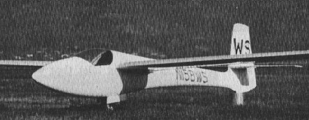
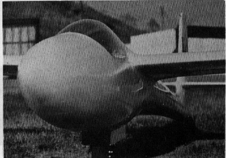
Figure 2 is the ship as it finally looked. Note that the nose has been changed, the canopy cut and shortened, and the piece added to the fuselage over the wing with a fillet, new wheel well doors, moving fillets in the flap area, a new leading edge on the wing, a fillet up by the tail,
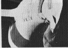
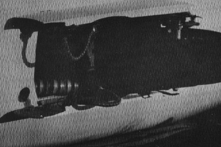
Figure 3 shows the exhaust that was spoken of earlier, under the tail.
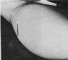
Figure 4 shows the way air is brought into the ship. The gear doors were replaced with larger doors shaped to form a very shallow scoop to pick up the boundary layer and direct it into the gear cavity and subsequently up into the cockpit. (You can also see a little bit of the wing fillet that was added on to the fuselage.)
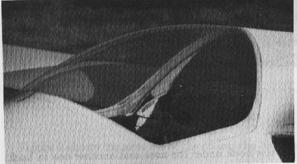
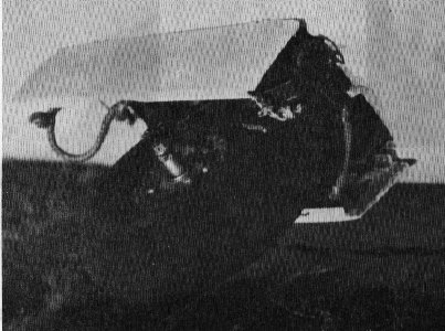
Figure 5 shows the canopy, note how it was faired in at the front edge so that it is very smooth. It was sealed very tightly all the way around, tongue and groove joints were added along the side to keep it from shifting position. There was a clamp inside to keep it down tight.
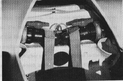
Figure 6 shows the cockpit. Note the top of the gear well has been modified too by adding a duct work to act as a vent. The air comes through the vents and attaches to the side of the inside of the canopy and acts to defog or deice rather effectively. It also shows the water ballast installation. We put water in it way back before we had much experience with water. I put in very large valves and also the tanks are rather large but the installation was successful.
Normally the Libelle had the tow hook under the nose and another one in back just forward of the wheel. We took those off and put the hook on the landing gear itself Figure 7 so the hook retracts with the gear.
Figure 8 shows the area aft of the doors, the holes are the dump chutes for the water ballast. When the gear doors close the whole area gets sealed up.
The first problem that we stumbled onto was the leading edge. The air foil on the Libelle turned out to be virtually identical to the latest series of Wortmann Airfoils which are going to be on the Nimbus, for instance. The Libelle airfoil was designed by Heutter and not by Wortmann. The only difference between the two is at leading edge region. The leading edge of the Heutter foil is much blunter and it tips up a little. This, coupled with the flap positions on the ship as it was delivered, resulted in the whole lower surface being turbulent at higher speeds. So I fitted on to the front of the airfoil the Wortmann leading edge, which made it essentially like the recent Wortmann foils. That worked out very successfully. The leading edge modification accounted for over 10% of the total drag reduction at 100 knots.
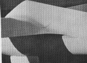
Figure 9 shows the front edge of the wing fillet, there is a piece on the fuselage and a little bit on the wing not very much. Now we can tape all the way around the wing because the canopy has been shortened. It also shows how much of a radius there is between the wing and the fuselage. You can also pick up a little detail of the flap wing junction. Figures 10, 11, and 12 show the area where the flap joins the wing. It is a pretty difficult problem to allow a smooth contour without any breaks as the flap moves up and down. Note that the gap between the flap and the fuselage has been sealed down to just a few mils so there is no leakage in that area. That is a particularly difficult problem to solve on the Libelle.
Figure 10 shows the ship in the maximum l/d or cruise position.
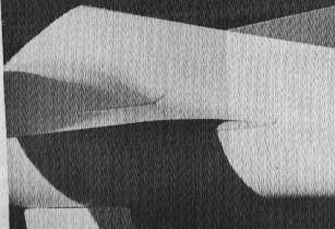
Figure 11 shows the flap in the up position; notice the gap is still Sealed all the way around.
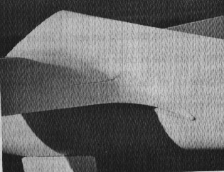
Figure 12 shows the flaps in the climb position.
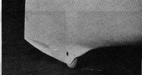
Figure 13 shows the tail wheel area. Note the exhaust fairing added to the fuselage extending the tail wheel fairing. We made the original hole at the very beginning and as we made more and more improvements it became increasingly obvious that this little hole was making an awful lot of noise. Then it dawned on me to add a little fin down from the rudder which formed a splitter plate which restricts the formation of vortices aft of the hole and quiets the noise. This is a very efficient way of dumping the ventilation air.
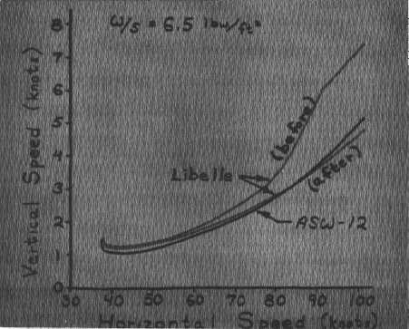
Now let us talk about performance before and after. Let us compare it to an ASW-12 curve (I don't want to say that these numbers are accurate to one percent, but they are within five percent.) The interesting thing about the Libelle curve Figure 14 is that it is not a smooth curve like you always see drawn for sailplanes. It comes up to around 75 or 80 knots and breaks rather abruptly to a much higher drag level and then continued on out. The break in the curve is caused by all the area that becomes turbulent. The wing became turbulent, the nose became turbulent, and the wing root problem began to become evident. These accounted for the extra drag. This also accounts for some of the history of the ship in competition. The curve shows that the Libelle is a very competitive sailplane up to about 75 or 80 knots. The place where this ship is very popular is in the east, where we do not have the strong conditions which tempt the pilots to fly at the higher speed range. At the higher speed in the Libelle you pay a large penalty. By eliminating these problems we have brought the high speed end up to where it is somewhat comparable to A.J.'s -12 (A.J. Smith's ASW -12). We compared it to his ASW-12 in actual flight runs. It is comparable to the "12" at 80 knots and seems to be perhaps a little better at 100 knots. Interestingly enough none of the modifications had any effect at the low speed end of the curve.
I think that pretty much covers what I wanted to say. I hope I have shown you that you can do some of this stuff yourself. There is no problem certainly with regard to determining what your problems are.
QUESTIONS AND ANSWERS
Question: What part of the thirty percent improvement came the easy way?
Answer: Ten percent or so came from the leading edge, six percent came out of the wing area. The wing area thing really isn't a performance improvement; it was just a discovery we made along the way. The wing fillet really didn't involve a lot of work. The rudimentary fillet, which was probably just as good as the final one, combined with the fairing behind the tail wheel and the little bit of work that was done on the nose, probably contributed fifteen percent summed up together. I don't have a breakdown on how each of those improvements helped.
Question: Did you seal the ailerons and flaps on the ship?
Answer: Not until very near the end. I personally have a thing in not believing in an air tight seal. I tend to like to use long rather close gaps to form what is really an effective seal. If you look at the amount of flow you get through a crack of four or five thousandths of an inch, at the pressures we are considering, it is almost negligible. So I believe in wiping joints which aren't actually physically contacting.
Question: I take it those are actual comparative flight tests that you make with the ASW-12?
Answer: They are comparative tests and there is some absolute data in that curve. There are three real good runs at a hundred knots, the data point at a hundred knots is really absolute. There are about four runs at 80 knots under different conditions. The principal run at 80 knots is a 35 thousand foot run in rough air. The data point that is on the curve there is a rough air point. So those two speeds, at least, are absolute on the curve and the other points are relative to A.J.'s ship.
Question: Is tape worth using?
Answer: Yes.
Question: What happens when you fix the flap on an open Libelle and fly it as a standard class ship.
Answer: The answer is that it is disastrous. If you plan to fly in standard class don't modify your leading edge.
Question: Can you provide an exhaust vent so you can use the provision for cracking the canopy for ventilation on an open Libelle?
Answer: I don't think so because the pressure field over the wings will suck the air out that gap no matter what you do and that is not good.
Question: Does the reentry angle on the canopy cause extra drag?
Answer: We probed the flow in front of the canopy and it turbulent quite a distance in front of the canopy, probably entirely because of the reentry angle. There is a side comment by Professor Al Ormsby who tells me the side vortexes formed of the side of the canopy caused by the reentry angle benefits you somehow in the flow around the wing root. I can't understand why it ever would, but there may be something to this.
Question: How do you open the area between the cockpit and the aft fuselage to let the air to the tail?
Answer: I took the door off. The one that is normally closed when you are flying.
Question: In regard to the nose modification?
Answer: I may have got suckered into something here. We have had one Libelle that has been checked. The normal nose has about a four inch radius. And anything less than a four inch radius is marginal as far as triggering boundary layer turbulence. I had done a lot of repainting in that area, changed the gear doors, etc. Every time you hit a rock or something you would have to redo it. I think that I may have raised a bump when sanding for the refinishing. The bump then caused the turbulence and the modification corrected it.
Question: How far then does the laminar flow extend since the modification of the nose.
Answer: Not very far; about half way to the canopy on the top and a little farther on the bottom.
Question: How about nose ventilators, are they serious sources of drag?
Answer: If the opening -allows unrestricted air flow through the hole it is probably just as good as a smooth pointed nose.
Question: Please explain in more detail the development of the idea to use dye for turbulent stream flow investigation.
Answer: This idea was suggested to me by Professor Al Ormsby after he had attempted to use tufts. The tufts were very unsatisfactory. We were flying so close we were scared half to death and the observer still couldn't seen anything significant. Then the dye showed the problem very plainly. The dye runs back and enough of it dries to show up plainly. It also washes off easily afterwards. You must be careful not to put out too much or put it out at more than one airspeed.
Question: What materials did you use to make all of the modifications?
Answer: I used polyester exclusively. That is not what Fred Jiran recommends. As long as your mods are non-structural, all my mods were non-structural, polyester works fine on a Libelle, as long as you make sure you clean off the mold release.
Now I have a Diamant and the polyester is useless in trying to attach to the epoxy it is made with. We have tried some test patches.
Question: What wing loadings did you use?
Answer: At times I carried as much as 240 pounds of water. I feel that for typical eastern conditions 100 pounds is plenty. The minimum wing loading was about 5.7 to 5.9. The maximum with the proper wing area, figure was up around 7.8 pounds.
Question: Didn't you try some tests either on purpose or inadvertently with one wing filled with water and the other empty? If so what was your observation?
Answer: Yes, this was in the early days of the water ballast idea. I was concerned about the flow from one wing to the other and the possibility of unsymmetrical loading. That was the original reason for using two valves. One day when I was high I dumped part of the water in one wing, and slowed up, went through a stall, etc. After checking that out, I dumped some more. The net result was that with one wing empty and 120 pounds in the other, I picked up just a very little aileron pressure. I tried it at all speeds and with the flaps up and down experienced no control problems at all. It took about a quarter of the aileron travel to balance that wing. I concluded that the water imbalance is not a serious thing as long as you know what happened.
Copyright Soaring Symposia Permission to copy this article is granted for non-commercial use, in its entirety, and with this copyright notice attached.